Sunday 19 March 2023

Do you want to run an Inverter

 The Inverter is an electronic device that converts a DC voltage to AC voltage. Cruisers usually want to convert ships 12 volts DC battery power to 110 or 230 volts AC. 

 We love having an inverter on board and it gets used on a daily basis, we do use the inverter to power the washing machine, kitchen and workshop tools and it really makes our life on board easier . 


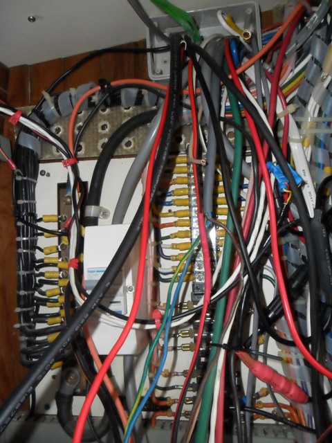
A bare bones Pure Sine Wave inverter fitted in Matilda. 

This inverter is a combi unit and includes a built in battery charger for when we are connected to the shore power at the dock. By bare bones I mean it does what its meant to do very well, it outputs a single phase  pure Sine Wave and charges the batteries when connected to the dock power. It doesn't have a lot of the bells and whistles that most cruisers dont really need. While they may be necessary for complex installations, for most of us they are unused and are just an added expense and that money could have been used elsewhere.   

--------------------------------------------------------------------------------------------------------

Before we get started basic abbreviations and power rating.

A well used electrical calculation:  Watts = Voltage multiplied by the current in Amps;  W = V x A

AC is an abbreviation for alternating current:   an electric current that reverses its direction many times a second at regular intervals, in Australia its 50 times per second and in the US its 60. also known as Hertz or Hz. Output is from a portable generator, inverter or mains (the big generator at the power station) 

The AC wave form, output from a Sine Wave Inverter or generator. 

DC is an abbreviation for direct current: an electric current flowing in one direction only. Output is from solar cells, batteries. 

RCD Safety switch: An RCD switch will operate when there is an imbalance in the current flow in the active and neutral conductors. Once this imbalance reaches the set threshold, usually 30mA, it opens the circuit, cutting the power output.  A lot of people believe that an inverter is safe and will cause no harm because it runs off batteries. However this is a false sense of security, the power from even the smallest inverter can kill as quickly as a mains power point. So it is certainly recommended a RCD safety switch be fitted.  For a discussion on safety switches

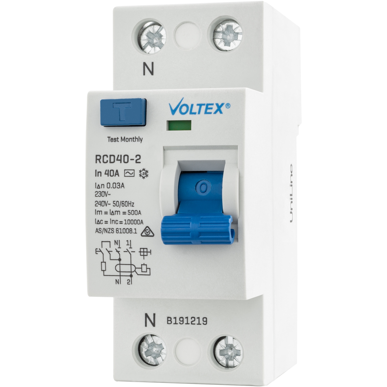
RCD Safety switch to reduce the chance of being electrocuted from the output of an Inverter

--------------------------------------------------------------------------------------------------------- 

Why have an Inverter when you go cruising?

In Australia we all have 230 volts AC as the primary mains voltage source at home, we already have many appliances that run off 230 volts, it may be the high powered microwave oven or the very low power charger for a laptop, tablet or camera. An Inverter allows you to use the appliances you already have when you are away from the shore power. The disclaimer here is that the inverter type and size has to be matched to the appliances you want to use.

Benefits of using an Inverter

Instant power with the flick of a switch, no turning on the gen set, or switching over the source of the power. The main reason for most people is that there is a wide variety of appliances. Using an Inverter can save you the cost of replacing the appliances you already have at home with 12 volt equivalents. In some cases 12 volt appliances are more expensive due to lower sales, or possibly they are not available for every application.

Why a lot of Cruisers buy an Inverter

A lot of cruisers like to take the convenience of household appliances out on to the water with them. There are so many appliances used in the kitchen or workshop that make quick work of tedious jobs. I use a powerful mixer on a daily basis to knead bread dough so we can have a fresh loaf of bread while we sail offshore miles from land. Using the appliance we reduce the kneading time from 20 min to just 5, not that we don't like the upper body workout, we like using that time to do other jobs. There is just about an appliance or power tool to help with most jobs, and we have met people who use some appliances we never thought of taking on board, it's only limited by imagination, storage and of course battery bank endurance.

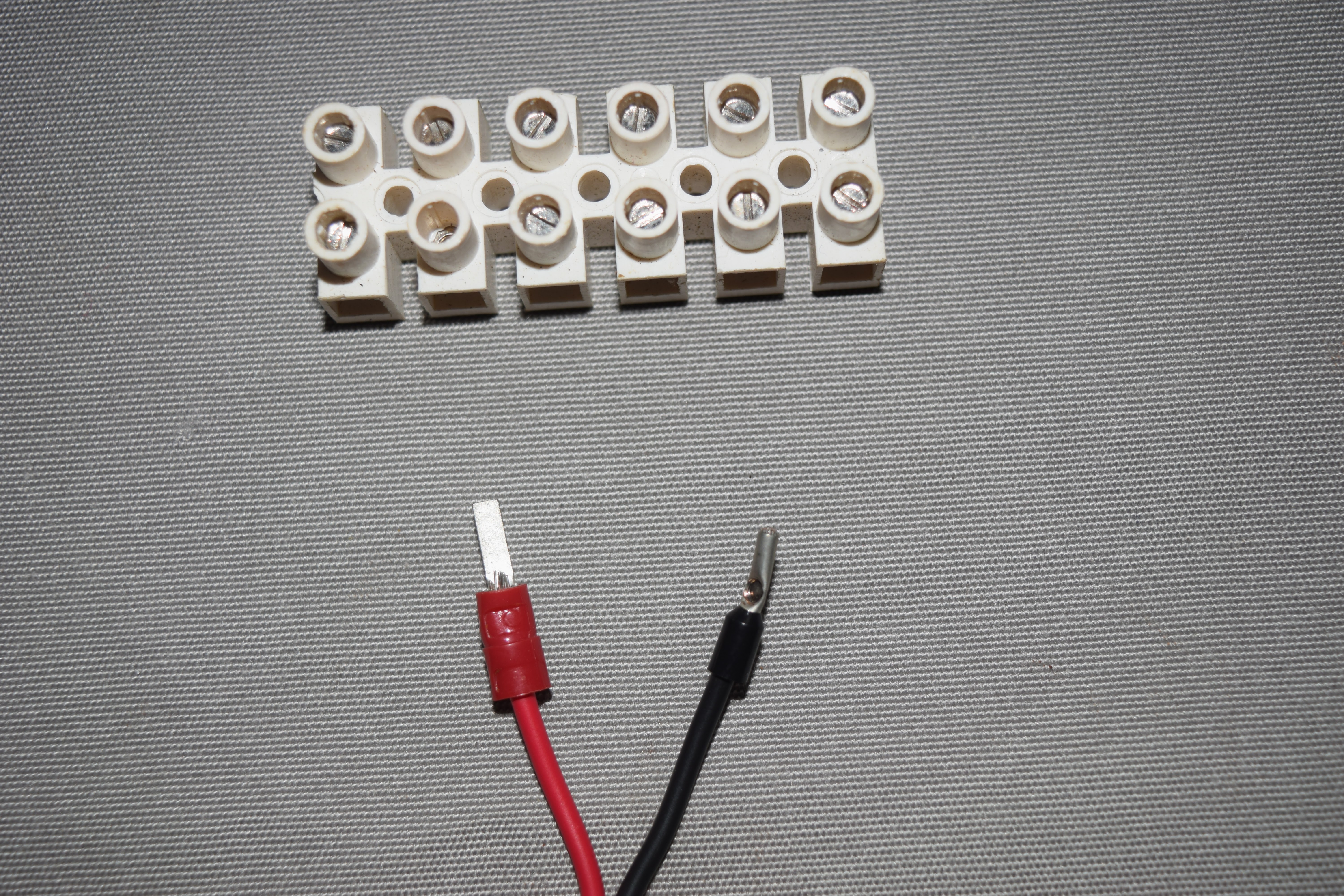
During our travels we have met with dozens of cruisers who had planned fitment of their inverter during preparations before going cruising. The cruisers then executed the install and had the 12 volt side of the inverter connected with the right gauge wire, fuses and safety grounds. They can also have wired in power points outlets to make the inverter use convenient. By having the inverter properly installed they were able to install and configure a RCD safety switch and circuit breakers to protect the people and appliances. Add on kit for an RCD info here

There is also another good reason a lot of people buy an inverter, they do not know there are 12 volt alternatives for the most commonly used items. So what are these commonly used items? most of the time its battery chargers (phones laptops, cameras) and TV’s, and this is why so many people buy an inverter, they head off to the marine/camping/electronics/tech shop to get something to charge their laptop, phone or even the head torch, and really the list is almost endless these days. The sales person quickly takes the customer to the inverter section and gets a quick sale. The customer goes home not realising there are other products out there that can charge and run their small appliances and in nearly all cases are a lot safer and much more efficient at doing it than an inverter. But more on that in another post.

Being on a yacht we want products that make use of stored electricity in the most economical and safe way. Unfortunately for just charging laptops, phones and these types of appliance, a small inverter isn't always the best and or safest option. This is why we feel its a great idea to have a balance of electronics to do the jobs on board. This way should the inverter fail (happens from time to time) you can carry on with minimal disruption. 

Please read on, for other uses an inverter can come into its own, if set up correctly.

Operation

A great reason for using an Inverter is, being much quieter than using a generator to produce the AC power, and when your running off batteries, there are no concerns about fumes or heat from the exhaust, and no flammable fuel to handle. If the generator isn't built in and running on the ships fuel, most of the small portable generators popular with cruisers run on petrol. This adds the complexity of firstly safely storing the generator and secondly the fuel to run it. The storage of petrol does have its complexities on a vessel designed and fitted out as a diesel fuel craft.

Versatile

An Inverter can be used whilst the vessel is running, and therefore not draining the house battery. Unless your a sailboat and having a good day out in a nice breeze. When motoring this has practical applications; ie arrive at the anchorage with fully charged batteries, camera batteries, laptop, and so on and so forth. 

For safety an Inverter must never be switched on when you go to start the engine unless you have a totally isolated motor start battery. If you don’t the surge of current required to start a boat motor can drop the voltage down below 10V DC. After the motor is running and the alternator kicks in, it will surge back up to 12 V DC, the combination of surges can damage the inverter, the appliance running on the inverter at the time or of course both.

Interpreting the numbers written on the inverter

An Inverter changes the voltage and current, the power it puts out is always less than the input power, due to inverter efficiency being less than 100%. Most, but not all inverters list the operating power in watts, a big inverter may output 2500 watts so if it really is outputting 2500 watts at 230 volts that will be 10.86 Amps output, just over the maximum of a standard power outlet in Australia. This large inverter is capable of running most appliances easily. However keep in mind most of the numbers on the case i.e. 2500, the inverter will not really output 2500 watts. One that I know of will output 2300 W and another that has 3000 on the case outputs 2200W, so the reality is that you need to read the spec sheet to see the real out put value.

On the other end of the inverter scale is small inverters with an output of, for example 300 watts, this will be 230 V at 1.3 amps, and would be enough to run most laptop chargers. 

An inverter is usually between 80% and 90% efficient. The 10 – 20 % of power that is lost as electrical energy escapes as heat energy in the Inverter. While this doesn't sound too bad if you crunch some numbers when operating at higher power it can be a significant current (in Amps) drawn from the batteries that is wasted energy. 

So as an example of power loss, if an inverter is drawing 100 Amps and is 80% efficient then 20 amps  will be wasted power and converted into heat. 

Electrical Power

Electrical power is usually measured in Watts (1000 W = 1 kilowatts, 1 kW). So to keep it simple an inverter that outputs 240 volts at 10 Amps is 2400 Watts (240V x 10A =2400W)

Some Inverters output are rated in VA (Volt-Amps) rather than Watts and for many appliances this will equate to the number of Watts with a power factor of blah blah blah, well beyond our ability to calculate the actual value. The simple truth of the matter is VA means nothing. If you want to know how much power your inverter is going to give you then ask for the rating in watts at 40 deg C, all the other ratings should be kept for the fairy tale books where they belong. Some brands of inverters have a lower value in the model name but, in fact, are the more powerful of the bunch when apples are compared with apples (watts with watts). So shop around for a unit where you get what you think you should be getting, and it does what it says on the box it does. Do the comparison in Watts at 40 deg C apples with apples, (watts compared with watts). I do know some manufactures use lower temp rating to give better figures, however unless your operating your vessel in the lab then the 25 deg C isn't really achievable. Its all in the advertised wording. 

Peak and Continuous

Two numbers are used to describe the output of an Inverter, Peak and Continuous.

Peak (or surge) describes the output deliverable for several seconds the Inverter components won't blow up at that amount of load, but they will heat up really quickly. Continuous ratings are usually limited by the heat that needs to be removed when running continuously. Ideally you would find out the Peak and the instantaneous ratings of your appliances and check that they were less than the Inverter output, but you can't rely on this because most appliances don't state the start-up or peak power and the length of the peak really needs to be known too. Unfortunately, the only way to be sure, is to test the appliance with the inverter.

For safety never run the inverter continuously at full power for long times, I have a safety margin in the order of 10% factored in to our calculations for long run times as this allows for the odd surge. 

Size of Inverter Needed

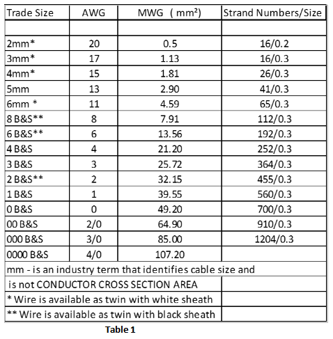
The following table is only a rough guide as there is a lot of variation in startup surge load and continuous load for similar appliances between makes and different models.

Size of Inverter Required Type of Appliance

150 watts - Charger for cameras, laptops, some power tools, DVD player; coffee grinder
250 watts - TV, slow cooker, desktop computer, electric blanket, kitchen mixer, printer
500 watts - Small fridge, freezer, small angle grinder, drill, TV, washing machine (no water heater)
1000 watts - Bread maker, low power microwave (some microwaves are very hungry appliances).
1500 watts - Small air conditioner, vacuum cleaner, small iron, pie maker
2000 watts - Microwave (1200 watts), hair dryer, fan heater, iron, electric kettle, toaster

Types of Inverters the all important “Wave” output

When generating AC from a spinning generator, it’s very easy to generate the sine wave that AC has, but when inverting DC to AC, the easiest wave shape to output is a square wave. Unfortunately a square wave has more energy for longer at frequencies other than the 50Hz or 60Hz (Hertz or Cycles per second), and this can cause problems of overheating in transformers and some motors.

A sine wave, this is the same power wave output at the mains power point on shore and is the same as output by a rotating AC generator, or a Pure Sine Wave Inverter. 

A comparison of the three waveforms laid on top each other 


Today Square Wave Inverters are rare except in the smaller sizes or the real cheap ones and most output either a Modified Square Wave (MSW) or a Sine Wave/Pure Sine Wave. Inverters advertised as Modified Sine Wave are just a marketing department creation and are really only a Modified Square Wave. Nevertheless modified sine wave (MSW) does have a good ring to it when you have been told that the sine wave unit is the best one to get.

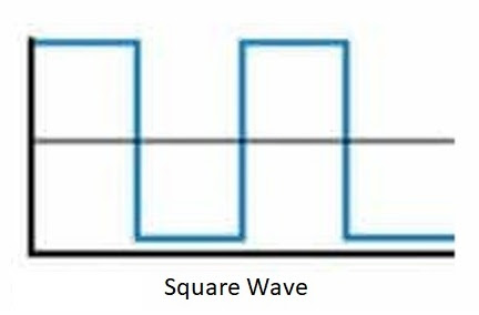
A square wave display, as can be seen this wave form quickly switches between positive and negative and stays positive or negative at full power for longer, this quick switching can overwhelm some electronic appliances connected to the inverter.  


Most small plug in pack chargers and power supplies for cameras, laptops etc these days use switching or switch mode power supplies. So how do we know if this is the case most of the time its in the weight, feel the weight of it and if it feels like it is full of copper wire it more than likely has a conventional transformer in it (most probably needs Sine Wave), if it is much lighter, then it is a switch mode. In theory the switch mode power supplies should work ok on any wave shape input, because they firstly convert the AC to DC, however if the components inside aren’t rated adequately, they may overheat due to the quickly fluctuating square wave shape.

Modified Square Wave Inverter (MSW) A.K.A Modified Sine Wave Inverter (MSW)

Most appliances will work from these basic Inverters, but unfortunately unless you can look at the internal electronic design of the appliance, you can’t be sure if you will really need a Sine Wave Inverter. The squarish wave shape can also confuse the timing circuits in some appliances that use Frequency as a timing control. If the appliance doesn’t work normally or makes unusual noises, then disconnect it or you may have expensive damage. 

These Inverters also generate more interference to TV's, AM and HF radio reception than Sine wave Inverters and can cause buzzing in CD players and stereos. 

When using an inverter in the marine environment tests need to be carried out to make sure the inverters electrical noise isn't enough to compromise reception on VHF frequencies used for radiotelephone, Digital Select Calling,(DSC) and Automatic Identification System (AIS).

Modified Square Wave AKA Modified Sine Wave, as can be seen this wave form is certainly has a lot quicker notchy rise and fall times when compared to the Sine Wave gentle undulation of rise and fall. Also keep in mind the number of additional steps in the modified square wave will influence how the inverter and connected appliances will perform. 

Electric motors for an example in washing machines, bread makers, power tools, microwaves, vacuum cleaners may give trouble if used with a modified square wave inverter. 

Can I run computers with my modified square wave inverter? Most laptop/notebook computer AC power adaptors work perfectly well with the Modified Square Wave Inverter. Desktop computers and some laptops/notebooks may be more sensitive so they may not function correctly or cause a humming noise, in which case a pure sine wave inverter is recommended.

Mac/Apple products are extremely sensitive in the way they use their power, and will require a Pure Sine Wave Inverter to run successfully. We also found a good power filter was also required when using apple products. 

You may have trouble using an AA battery charger with any inverter due to the way the battery chargers draw energy. You will also find that a pure sine wave inverter is a better option for battery chargers due to the fact that there's much less ‘electrical noise’ interference compared to a modified square wave inverter. This ‘electrical noise’ can often wear away at the sensitive components in lower quality battery chargers. The rechargeable batteries, recharging transformer and Inverter may be damaged when trying to recharge devices of 10 volts or higher.

However, it is always a good idea to double check your appliance's manufacturer's guidelines first. If they can't be charged via a modified sine wave inverter, they will mention something similar to "Charge via Mains power only" or not as we have found out.

Sine Wave Inverter (marketed as Pure Sine Wave or Pure Sine or even the S model)

Sine Wave Inverters are more expensive than Modified Square Wave, some times up to twice as much because more components are needed to electronically generate the Sine Wave. You may consider that If the appliance has a Transformer or an Induction Motor think washing machines and appliances listed earlier, then it most probably needs a Sine Wave Inverter to prevent overheating. Now this is not always true, since some fridges and freezers can work fine off Modified Square Wave inverters, and in fact you shouldn't really notice any difference powering a fridge from a Modified Square Wave inverter, however the notchy waveform can interfere with timing circuits.

The wave form output by the an inverter, same shape as the mains power from shore. 

-------------------------------------------------------------------------------------------------


A list of optional features that are listed as inverter options/specifications.

Isolated Input-Output
If you are using only double-insulated appliances (i.e. they have no third Earth-pin on the Mains plug) with your inverter, then it doesn’t matter to the appliance if the inverter has total electrical isolation between the DC input and AC Output (provided there is no fault to earth). In larger installations with an earthed neutral, or if you have earthed appliances such as Washing Machine.  If the Inverter input and output is not isolated, the DC input (battery power 12V) will be up to 115-120 volts AC above the mains earth and this is a very dangerous situation. The out come could be …….. see the next

Electrocution I am lead to believe from years of health and safety briefings it only takes 35 milliAmps (that's 0.035 Amps) in the right conditions to kill a person. The 230 volts from an Inverter can kill you instantly, just like the 230 volt at home, so you need to take precautions. So if you do purchase an inverter that doesn't have total electrical isolation between the DC input and AC output there are several things to do for your safety.

1. Don't use it, return it to the store for a refund, probably the safest but most ignored advice.
2. Make sure the appliance you use doesn’t have an internal connection from earth to neutral.
3. Make sure any appliance is double insulated and does not have a ground pin on the plug.
4. Never make live connections e.g plug in the appliance when the inverter is running.
5. Never disconnect a running appliance with the inverter running.
6. Never work on the batteries or battery connections with the inverter running.

Earth leakage protection or RCD (residual current device)
Bigger Inverters may have these built in, however if not, there are kits available so it can be easily added so operators (consumers i.e. you) are protected by an RCD safety switch and overcurrent circuit breaker. However you cannot get this level of protection unless the inverters input and output are isolated.
A RCD safety switch, while we will never know for sure, we believe it saved us from a nasty accident when our washing machine developed a fault, and another time when I accidently dropped the hand mixer into the sink full of water and with out thinking tried to stop it sinking. 


Earth – Neutral link
An automatic earth to neutral link when on inverter mode (no shore power). When disconnected from shore power the unit makes the earth to neutral connection so RCD safety switches can operate.

This feature is also very important if the inverter is also a battery charger when plugged in to shore power. Most are marketed as combi units to designate an inverter and battery charger combination. When the unit is plugged into mains power the connection from earth to neutral is turned off to make use of the earth to neutral link from the shore power receptacle/power box, this enables the shore RCD safety switch's to work. 

Soft Start
Some loads draw much more current when starting up compared with steady operation e.g. an electric kettle draws a lot more current when first turned on, and motors can also draw very high currents as they come up to operating speed. To reduce these massive current surges, some Inverters bring the output voltage up to full voltage progressively over several seconds. This means you will be able to use an Inverter with a smaller continuous power rating, for a particular load.

Low Voltage Cut Out, Shutdown or Battery Disconnect
To prevent damage to your battery, it’s important that the Inverter can switch itself off and remove all current drain, when the battery voltage drops below a set limit. It helps if the cut off voltage can be set by the user, based on the type of battery. Keep in mind that as battery voltage drops, the inverter will draw more current to keep the output power constant. This means that voltage will drop a lot quicker as it reaches the point of full discharge, therefore manual monitoring of battery voltage is not really practical.

Automatic Fan Cooling
To keep the internal components operating properly the waste heat in inverters must be controlled, it is imperative to have an internal fan that is automatically switched on at a set temperature when needed.

Meters 
You can get by without voltage, current and a frequency meter, but with them it’s easier to check if your system and appliances are healthy, or if you’re close to overloading your Inverter. 

Autostart (may go by different names)
Some larger Inverters automatically can sense when any appliance is connected or switched on, so that the inverter only draws significant power when it’s actually needed. This is particularly useful in larger vessels, caravans or buildings, because you don’t have to switch the Inverter off and on when using appliances.

Not all manufacturers include an Auto start feature especially when it comes to Pure Sine Wave inverters, some have a hard wired remote and the more modern units Bluetooth. The major drawback to this auto start feature is the power used while in standby. This can be significant and should be included in the planned daily power usage.

Remote Control
For inverter installations in vessels, caravans or buildings, it’s handy to control and monitor it remotely, the inverter should be mounted in a cabinet near the batteries to simplify and shorten the wiring necessary to connect the batteries to the inverter. Installing the inverter close to the battery, will allow you to minimise the amount of heavy cabling that is needed in the 12 volt part of the circuit. For operations the remote should also function to alarm fault conditions to the operator.

Inverter/Charger (combi units)
For permanent Installations, the Inverter may be able to charge the batteries when mains or onboard generator is available. These units are sold with a variety of current outputs for the charger, most have the function to connect a remote monitoring panel. Most are advertised as Combi units due to the combination of charger and inverter. They can simplify the connection of shore power due to being an automatic switch between inverter and shore power. No need to clunk over a heavy duty switch to select shore power or inverter. A separate battery charger is no longer necessary.

Some units also switch the Earth Neutral connections so RCD switches work as intended, very important for crew safety.

Overload cut-out
The more sophisticated inverters will protect against over temperature, current, voltage or under-voltage, any of these conditions can cause damage to the inverter or the appliances connected to it.

Overheating of Inverter & Wiring
It’s important not to install Inverters in confined spaces where the heat can’t escape, either through air movement or conduction. It’s very important not to cover the case of the inverter or obstruct any fan intake for example by mounting it too close to a bulkhead or furniture. Never mount an Inverter in the engine compartment, I know some vessels have very large engine bays and I would make sense to mount them in this space. However a separate well ventilated insulated compartment should be constructed to keep the heat of the engine room from entering the well ventilated cabinet.

Twelve volt inverters, can draw high current from the battery banks, the general rule is to divide the output power by 10 to understand how much current will need to be supplied. So a 1000 watt inverter will draw 100 amps from the battery and this means using battery cables which can supply this level of current without overheating, while also keeping total voltage-drop in the positive and earth lead to less than 1.5% in each - i.e. less than 0.2 volts.

Inverter Grounding

I am sure most of us know the high voltage of the AC system presents a shock hazard and can certainly be lethal. The DC system is not normally an electrocution hazard but can provide a lot of current, and so is potentially a source of fire. A suitable ground must be installed between the AC and DC system. During my inverter fitment I noticed in the operating instructions the requirement for grounding connections on both the AC side and DC side of the unit’s case. This grounding can prevent shocks from AC, and fire hazard from DC. 

My previous unit only had the  smaller AC grounding connection made. A fault in the DC side of the system could provide enough current to overheat the AC grounding conductor (think enough heat to melt insulation and start a fire) without blowing the large DC fuse. Keep in mind the fact that the AC ground is not fused and current will flow through the conductor until it burns out. A high amperage capacity DC grounding path back to the DC system should be made. The conductor size for the ground needs to be of sufficient cross sectional area (bigger is better) to be able to sustain enough current to blow the supply fuse.

The installation instructions for older inverters (as I had previously) typically do not include this precaution, but most newly designed units do. Though looking into some different manufactures install instructions this connection is not addressed in any depth, most only state or draw the connection in on the installation schematic. Due to the fuse size in my inverter we needed a 70 mm2 ground wire for the DC ground. 

Limitations

Battery capacity

All the power for the load has to come from the battery, so with high power Inverters or appliances you want to run for a long time, you need large battery banks. If you wanted to run a small Air Conditioner that used 1000 watts on average, it would draw 84 amps, so you need to have a battery bank capable of supplying 2000 amp hours in a day. However we are not done yet, we still need to factor in the losses incurred (the 10-20% mentioned earlier) by running the 12 V DC through the inverter to output 230V AC the figure would be closer to 2400 amp hours draw on the batteries. That means big, heavy and expensive batteries, more importantly a way of recharging them or keeping them charged.

----------------------------------------------------------------------------------

Alternatives to an inverter

Use 12 volt appliances

Many appliances are available as both 12 volt DC or 230 volt AC versions, but the 12 volt version uses less power and is always more expensive. A 12 volt fridge will mostly have thicker insulation and use a more efficient motor/compressor. The designers of mains powered appliances don't factor in the same level of efficiency as they do for 12 volt powered appliances, due to the design spec being for an unlimited mains power source.

A 12 volt electric kettle will use less power because there are no losses in converting the 12 volts to 240 volts first, how ever a lot of people don't actually realise how much power an electric kettle draws and the install of the unit can be more expensive due to power cable size. Using only 12 volt appliances, may reduce your power needs, so you won’t need a generator or run the motor to recharge your batteries on shorter outings. However you need to ensure you use heavy enough cable to run the appliances connected to them. 

Generator

These can easily generate the high power level often needed and they produce a 230 volt output directly. However an inverter is totally silent and much smaller than a generator and doesn't need regular servicing. Keep in mind that most portable generators exhaust can output deadly carbon monoxide gas and in the right conditions this lethal gas can find its way below and slowly kill you while you cook dinner or have a few beers.


Monday 6 March 2023

Electrical Work, Wire, Terminals and Tools


For many years my job had me installing all manner of marine electrics and electronics in vessels located at different ports around the world. I didn’t think that purchasing the right size wire, terminals and tools to do electrical work on my vessel back here in Australia would be very difficult. However, I thought wrong, as I found out it’s not a simple task for the average cruiser to get all the right equipment together. When I was preparing to do upgrades I didn’t realize that I was about to go on a steep learning curve. I knew what I wanted from measuring the cable runs and then doing the voltage drop calculations. I simply thought I could write out a shopping list and go along to the chandlery or auto/electrical supply store and get what I wanted. Unfortunately due to the way wire is marketed here in Australia purchasing wire requires greater care, but more on that later. The flow on effect of differing gauge can mean it’s easy to make mistakes and use undersized wire or perhaps crimp on terminals meant for larger gauge wire.

This is going to be fun they said, just a little bit of rewiring they said. Its amazing how a little bit of electrical work requires lockers to be emptied to do the job properly, but done properly and the job should last until the equipment is derigged.   

A lot of the easily accessible information on line or in books is for equipment and materials manufactured and marketed overseas. The same can be said for the information supplied by company’s making wire, terminals, tools and marine components. Perhaps it’s also a sign of the times where most of our tools are imported and it appears they have been manufactured for sale in a global market place so at times they are not an exact fit to products produced here. This does not make it easy when we head off to the chandlery to purchase bits and pieces to do an install or repair job. So as I collected information I assembled this assortment of cross referencing information into a format that I hope will make it easier for us to get our head around. I know most sailors will head off to the local chandler when they need marine wire. With that in mind I have tried to incorporate the most commonly stocked wire sizes into the calculations for current handling and crimp terminal sizes.

As the electrics on the average cruising boat become more advanced the one thing that has always been a requirement for reliable operation is the need for electrical installation or repair work to be done neatly and efficiently. To do this correctly you will need to plan the job, have the right tools, wire and the correct terminal fittings. It doesn’t matter whether you’re installing new electronics, electrical gear or rewiring something already on board, the necessities for safe, dependable and secure electrical connections are the same, do it right the first time, using the correct gear.


Who ever did this job didn't plan very well, the electrical cabinet looks like it vomited a techno colour of wire. If your thinking of buying a boat where the electrical cabinet looks like this, you may find its only the tip of the iceberg and putting it right may be costly, time consuming or both. 

Plan to do the job correctly to start with, make operation easier, and a lot more reliable, nothing worse when turning on a bilge pump to find it not pumping, or getting close to dark and all the nav lights stop working, Sadly the person who did this fantastic job didn't have a plan or a clue. yep fun times can be had by one and all in the aftermath of a job like this. 

Planning the job will save you a lot of hair pulling later. Take time and explore your options to decide how the new equipment will be installed. The plan should include where the equipment will be installed, what interfaces to the equipment and is access to the newly installed equipment reasonably easy. Where is power to the equipment going to be run from and how many amps are required? These are a very important questions that will need answers for proper installation.

Only you can really decide where the equipment will be finally installed. Then once that’s done the next important consideration is the length of the cable run. Not just an as the crow flies type of measurement but take all the curves and up and around and through cabinets and cable trunks type of measurement. By taking current draw (Amps) and cable length into the calculations the correct size wire can be purchased and run. But don’t buy cable just big enough for the job, you don’t want the wire to be running at one hundred percent of current carrying capacity. Go the next size up for redundancy and remember the bigger the wire the less resistance it will offer a load and the easier electricity will pass through it, and the cooler it will run. A win win situation for all.

I have mentioned safe electrical installation, keep in mind several vessels are lost each year due to electrical faults. If doing electrical isn’t your forte then before applying power it could be worthwhile to have a friend to look over the job before you throw the switch.

Wire Gauge

The term wire gauge refers to the conductor cross sectional area of a wire. Wire gauge can be used in calculations to determine electrical resistance and the current handling capability.

In Australia there are several means of describing wire gauge for wire used on recreational vessels, the most common are Trade Cable Diameter, MWG (Metric Wire Gauge), AWG (American Wire Gauge), and B&S (Brown & Sharpe). B&S is equal to AWG. B&S has been commonly miss quoted as battery and starter, or perhaps this label is used to sell a product that is not sized correctly.


Cross section of cables and bigger is better, however this is an example of cable size, the larger cable is sold as 70mm2 which is equivalent to 00B&S or 00AWG and is actually 64.9mm2 and the smaller cable is sold as 35mm2 or 2B&S or 2AWG  and is actually 32.15mm2 great stuff !!

Trade Cable Diameter is commonly used to market automotive/marine wire in Australia. This is a trade unit referring to the total diameter of the cable to the outside of the insulation, closer investigation is needed to find the cross sectional area of the wire conductor before calculations for current carrying capacity can be carried out. We will mostly need to convert from Trade Cable Diameter to MWG (Metric wire gauge) which measures the cross sectional area of the conductor in mm². Metric wire gauge is used in several countries outside of the United States.


Here is the type of cables most Australians will find on the shelves of their local chandlery. There is also usually single wires in red, black with out the outer white jacket. These are marketed as 4mm and 6mm however this is misleading and is explained in the following text. Also of note is the total lack of marking on the jacket of the wire explaining the actual cross section size, maximum temperature and  voltage 

Good quality cable stamped with size temp rating and maximum voltage

AWG (American wire gauge) is most commonly used in the United States and because of the size of the market, manufactures all over the world compete and manufacture goods to their specifications for sale on that market. One thing that is usually evident with wire made for the American market is; that in most cases the size of the conductor and the temp rating of the insulation is stamped on the jacket of good quality marine cable and wires. The AWG is determined by the cross sectional area of the conductor and doesn’t include the insulation, the same as MWG however AWG is described using a list of defined standardized gauge numbers. AWG gauge numbers work in the opposite direction to MWG, with the smallest numbers representing the largest diameter wires. For example 6mm Trade Cable Diameter has wire with a cross sectional area of 4.59mm² (MWG) and this is roughly equivalent but on the small side to 10 AWG. The next popular size on sale at the chandlery is 4mm Trade Cable Diameter, this has a conductor size of 1.84mm² MWG and is equivalent to 15 AWG.

B&S is commonly used for marketing heavier wires and cables in Australia, I guess this is where the confusion and tie up with batteries and starter came about. As mentioned earlier B&S follows the same gauge descriptions as AWG and is simply another way of explaining the wire gauge. As an example 2 AWG = 2 B&S, 4 AWG = 4 B&S and so on.


Wire

As we know wire could hardly find a more unforgiving environment than on board a yacht. On board wiring has to be able to deal with the high humidity and consistent vibration, and be able to recover from the odd submersion as well as heat and cold from all manner of sources.

Wire used on a boat must be copper, though even copper has been known to corrode in the harsh marine environment. The most common cause of electrical wire failures is primarily corrosion and secondly poor work practices installing terminals and wires. I am sure we have all heard of tinned copper wire and we will need to pay more for the advantage of having the wires tinned during the manufacturing process. Tin plating each of the multiple strands of the wire with a coat of tin dramatically improves corrosion resistance. The additional cost of tinned wire is worth every additional cent because the anti-corrosion benefits are substantial. While the cost savings of buying untinned wire in the auto electrical section of the car parts supplier looks tempting, try not to justify this false economy. The cost savings are usually short lived due to the high failure rate of untinned wire.

Choose your wire carefully. Never use solid wire or wire intended for wiring a house. Vibrations will eventually fracture solid wire. It doesn’t need to be high frequency vibrations, wave motion is enough to flex all the wires on the vessel even if you don’t feel the movement. Boat wiring must have the flexibility multiple fine strands provides. The insulation covering the wire used in house construction is different to cable intended for the marine industry, so this is another reason not to use house wire on the vessel. Marine cable uses heavy tin plated annealed copper wire formed in such a way as to reduce capillary action of moisture within the cable. The flexible stranding (multiple fine strands) helps withstand fracturing due to the movement caused by the marine environment. Good quality marine cable has high temperature insulation to withstand the high ambient temperatures of enclosed engine bays. Depending on the brand some offer V75 (75 degrees C) and I have seen other suppliers/manufactures who market V95 cable. Where is your cable going to run? If it’s through the engine bay wire with the higher temperature rating specification could be the better option. Don’t use wire in an engine bay if you have no idea of the temperature rating of the cable insulation jacket, it’s just asking for trouble.


Wire. Twin sheath wire  red and black  conductors are encased in a second layer of insulation, both conductors in the sheath are the same size. These are multi stranded tin plated annealed copper wire formed in such a way as to reduce capillary action of moisture within the cable and are suitable for boat wiring. 

Most work for rewiring or installations will require two wires one positive and a ground (return) of the same size, don’t fall into the trap of believing the return wire size is insignificant, its size has to be equal to the supply wire. Twin sheath wire where the twin red (positive) and black (ground) conductors are encased in a second layer of insulation. This is convenient and provides the added safety of that second layer of insulation. There is also imported twin sheath wire with red and yellow conductor insulation, this is usually wire made for the American market due to their marine colour code where the black insulation colour is the active wire in an AC circuit. There is single wires and a three core wire for use on extra low voltage work on board, the wire colours vary with supplier but white, brown and yellow is common.

Size

As discussed earlier, wire sizing in Australia isn’t easy for the average yachty to get their head around the way wire is marketed. Unfortunately this mish mash of labeling requires careful investigation of the product to ensure it meets the correct size specification for your application before handing over your hard earned money.

The bigger the wire is the easier electrical current will flow through it. Some voltage will be used up pushing the current through the wire. This loss, called voltage drop, should not exceed 3%, for most circuits. However there is some equipment that won’t mind a slightly lower voltage, the only way you will know this fact is to look at the equipment specifications sheet supplied with your equipment. It is essential to use wire sized for the maximum current flow you expect it to carry. If the wire supplies a single unit, the current requirements will be shown on the label on the unit, or in the installation/owner’s manual. While a 3% voltage drop sounds like it would be easy to achieve remember 3% of 12.6 Volts is a drop of .38 Volts. So the voltage at the other end of the wire at the appliance when running under full load should be at a minimum 12.2 Volts.

To arrive at the length of wire used in the calculations for the correct size wiring, you need the wire length from the power source (circuit breaker) to the unit and back to the power source. As explained earlier not just a as the crow flies type of measurement. You must determine the actual length of the wire by measuring along the path it will follow-up down, over, and around. I have found in most cases that it’s not unusual for a wire run to be more than double the as the crow flies distance.

Not all (I haven’t come across any) electrical wire made to Australian standards as appropriate for marine use will have the gauge designation and temperature rating printed on the insulation, on the reel yes but not the cable its self. Perhaps the Australian standards and the manufactures need a kick start, this is a really poor/bad state of affairs. You will find that the best thing to do is to label the wire after purchase so it does not cause confusion at a later date. If you have purchased imported wire remember the smaller the gauge number, the larger the wire diameter.


Australian Manufactured Wire.  A mystery once off the reel.   No identification for size or temp value only a mark where the retailer should cut metre length markers

When purchasing wire for a job, buy wire at least a six hundred millimeters longer than your measurement. You can easily shorten the wire after it is run but lengthening requires a splice. Each wire should be a single continuous run between terminals, this helps keep the moisture out of the cable length.

When you do your calculations and head off to the chandler to buy the wire for your job, beware of the misleading marketing used to sell wire. Some rolls of cable will have current carrying capacity on the reel or in the store catalog, these calculations don’t come with any information as to the length of the cable run or the voltage drop calculations.

Wire sizing Reference

Table 2 shows what size wire is required to deliver adequate voltage to the other end. Use the maximum current draw of the equipment to select the row and the round trip wire length to select the column. The number where these two intersect is the wire size you need.

I have tried to simplify the wire sizes to the ones commonly held in stock at the chandlers. The numbers with mm (e.g. 6mm) is the normally advertised (Trade Cable Diameter) cable size, this is not the cross sectional area.

Wire sizes without the mm are B&S measurements. Remember B&S = AWG sizes. Cables less than 8 B&S are available in the white twin sheath; cable sizes 8,6,2 B&S are available in a twin with black sheath but not normally stocked in most chandlery’s but should be available so shop around. For better protection when using single layer insulated cables the cables will need to be run in conduit, cable trays, loom tube etc.

In table 2 the Round-Trip takes into account the total wire length (both wires) in the circuit. So an instrument three metres from the power source will at minimum use six metres of wire in the run, three metres of (positive) wire from the circuit breaker to the unit and three metres back to the ground bus to complete the circuit.


The Right Tools

The cost of the tools now days is nominal, however there are some very good trade quality tool out there costing a lot and for very good reason, they are made for day in day out work. For the amount of work most of us do on our vessels I don’t think the out lay would be justified and is more than we need to pay. Beware of clever advertising, I have seen tools that I would say are really poor quality advertised as tradie tools. The slightly better tool with several additional functions are marketed as professional tools. Do your homework before splashing the cash and you should be able to get tools that are easy to use and provide trouble free service. I would even go as far as asking the sales assistant for a demo. Yes I bought a crimp tool that was the be all to end all, what a disappointment when I got it out of the box at home and found I would need handle extensions to make it work. What upset me the most was that I had to pay a restocking fee when I returned a tool that clearly didn’t work.


Wire stripper: We should all have a good quality insulation wire stripper in the tool box. Stripping insulation with an inappropriate tool can result in a nicked conductor; or damage to the insulation. Nicking through the tin coating opens the gate to corrosion at a later date. Or on the other hand if the stripper damages the insulation there is the possibility of this hindering your ability to complete a proper crimp and the flow on result, a compromised join.


Wire struppers for most smaller wire work, with the bigger size cables I use a electricians pocket knife. 

Something to be borne in mind is that strippers sold in auto supply, hardware and tech stores can be for a variety of wire types. To clarify, I mean wire manufactured to the different standards, I have only touched on the most common types. You may find your strippers are marked with SOL and or STR, confusing unless you know that SOL stands for solid wire and STR is short for stranded wire. We should never use solid wire on a boat so buy stranded wire and use the STR marking slot. The next hurdle is going to be whether the strippers are for AWG (American Wire Gauge), or MWG (Metric Wire Gauge) or has the tool been made/marked to be for both. Now the thing here is who did the calculation and did they round up or round down when doing the cross reference. The best thing you can do is once you find a set of strippers you like is to do some test strips to make sure you don’t nick the conductors or reduce the size of the wire by accidently trimming the conductors and mark them up for your use. I found a set that works well and is marked with both AWG and MWG, I still have to be careful when using them to make sure I don’t scrape the tin off several of the conductors but I know they are not going to reduce the size of the conductors by nicking off strands of wire.


The Table 1 has a reference between the different sized wires so selecting the right slot on the stripper can be done easily.


Crimp tool: You absolutely cannot make a dependable crimp connection with a pair of pliers or a set of multi-grips. However reasonably inexpensive (not ratchet) plier type crimpers normally sold for the automotive industry, if used correctly can make satisfactory crimp connections. There are different styles of crimpers, it’s not a one style does all. Some are for insulated terminals only and others feature jaws/dies for insulated terminals and non-insulated terminals. One rule you will need to follow is to know how to use the tool and make a few practice crimps first. However you cannot beat a ratchet crimper, this style of tool offers the advantage of not letting you produce a crimp that does not have the required tension. That is as long as the wire and terminal sizes have been matched correctly. A ratchet crimper offers the benefit of consistency if used correctly. Just so you are aware, having a better tool does not guarantee perfect results every time, but practice first and you will be producing good crimps in no time.

Tools. Top Uninsulated Crimper Middle Insulated Terminal Crimper Bottom Special Connector Uninsulated Crimper

I could just leave it here as a general piece about crimp tools, but and there always is a but, crimp terminals come in a variety of styles. The problem is recognizing the type of crimp you have so you can match it to the correct tool. Hopefully the next paragraphs will shed some light on the styles and what tool to use.

Ok here is a crimp tool that will do the job in an emergency. They are good if you need a tool that can strip and crimp, they do require a lot more work, and strong hands.  They allow shoddy work or crimps not put on with sufficient force due to not having a ratchet function  They do however have a very handy feature if you need to trim off machine screws they can have a cutter function built in to trim screws off no filing or messing about once trimmed to length the nuts will go straight on. 

Terminals

Terminal Styles: insulated, insulated shrink tube, un-insulated, cable lugs and un-insulated specialist connectors.

Insulated terminals can be easily identified by the coloured plastic boot on the end of the terminal. It doesn’t just stop at just a plastic boot however, depending on the brand some have additional tinned copper sleeves under the plastic insulator. The colour of the insulated sleeve on the terminal will denote what size wire the terminal is made for. If you haven’t had a lot of exposure to crimp terminals you may not realize the plastic sleeve serves a couple of purposes. Besides insulation and identification, one important aspect of the sleeve is that in a properly crimped insulated terminal the sleeve acts to relieve the stresses placed on the wire where it exits the insulation jacket. This will stop unnecessary stress on the wire due to vibration or movement when connected to a terminal block, without strain relief the wires may fall off the back of the terminal after a short service life.

Insulated adhesive lined shrink tube terminals are colour coded like their cousins, the difference is the shrink tube is transparent and a larger diameter than the standard insulated terminals. These terminals are not a bad idea on a boat, they offer a level of strain relief not achievable with standard insulated terminals. However they do not create a water tight seal at the end of the cable but they will stop water entering between the wire insulation and the tubing. Greater care will need to be exercised when using shrink tube terminals so the tube is not damaged. A single jaw crimp tool must be used, not the dual jaw/die as would be used with standard insulated terminals. The other way to achieve a heat shrink strain relief is to apply shrink tube over the crimped insulated terminal and shrink it down.

The colour code for the insulated terminals is: Trade size wire MWG

Red wire size min: 0.25mm²- max: 1.65mm² 2mm & 3mm 0.5mm² 1.65mm²
Blue wire size min: 1.04mm²- max: 2.63mm² 4mm 1.84mm²
Yellow wire size min: 2.63mm²- max: 6.64mm² 6mm 4.59mm²

Insulated crimp terminals of various sizes and styles.


Uninsulated lug the ones shown above have a seam that is easy to see, mostly this style of lug is for smaller diameter wire. 

Uninsulated lugs come in a few different styles, some are made for specific wire sizes and the hole diameters on the ring terminals. When using un-insulated terminals if the crimp barrel has a seam, the crimp indent should be made on the opposite side, mostly the seam is easy to see.


A uninsulated terminal, the indentation from the crimp tool is made on the side opposite the seam as can be seen here. 

Uninsulated terminals can be used to form a very robust connection. Firstly crimp on an uninsulated terminal to form a mechanical connection on to the wire, then solder the tip of the wire to the terminal. When the terminal cools slightly install adhesive lined shrink tube. Once shrunk down it will create a good strain relief that under normal conditions is a water tight seal on the end of the cable. There is a bit of conjecture about solder, and that it is not as good a conductor as copper. While this may be, the connection is already very good due to the crimp, the solder is just additional and is excellent in the marine environment because it can keep moisture out of the end of the wire terminal.

Trim the insulation from the wire make sure it is not too long and the length should fit into the barrel and not protrude more then a mm out the end. Then put on the heat shrink and crimp the lug into place. 

Apply solder to the end of the wire to seal the tube and wet the wire inside of the crimped connector

Apply a little more heat to wick the solder into the connection, most times its possible to see the solder start to show between the insulation and lug, stop here you don't want the solder to wick too far under the insulation.

Shrink the adhesive lined shrink tube over the end of the lug and onto the insulation. This connection should be sealed enough to stop water or moisture from wicking under the insulation corroding the wire

Uninsulated terminals on a short wire, adhesive lined shrink tube used as a sealant on the connection and doing a double service as strain relief of the join between the wire and terminal


Heavy duty cable lugs, a large crimp tool is required to make these fit properly on the cables. Depending on the crimp tool 2 or 3 crimps evenly spaced along the body tube is necessary to execute the proper crimp connection

Uninsulated lugs, heavy duty, the cable size and hole size for the stud is marked on the lugs. In this case in mm² & millimetres 


Specialist uninsulated crimp tool, seen here with the contacts and shell of a multi contact connector housing

Other terminals are made for use with specialist crimp tools, these terminals are made for plastic boots to be fitted over the cable insulation before crimping the terminal on, then slid over the crimp once finished. These crimp tools can also be used to install the specialist terminals when assembling multiple contact quick connect plugs and housings.

 Warning you do get what you pay for

A word of warning you do get what you pay for when crimp terminals are concerned. Terminals sold cheaply at the local electronics enthusiasts or vehicle accessory store may not be a very good choice. In a lot of cases they are not tinned copper but a copper alloy blend, they are hard to crimp both physically and mechanically and in service offer poor corrosion resistance.

Crimping

Strip enough insulation for the wire to reach the end of the barrel of the terminal inside the insulated end. Grip the terminal in the correct crimper slot, fully insert the wire into the terminal. It’s time to eye ball your creation before squeezing the trigger on the crimp tool. Make sure enough wire is inserted into the terminal barrel, if you are using fully insulated terminal and cannot see the end of the wire try the wire for size in an open terminal to be sure. Too much insulation stripped off can be as bad as not enough and could lead to a compromised crimp job. When using insulated terminals no bare wire should protrude out from the terminal. Have another quick look hold the wire into the terminal and squeeze tightly.


Insulation stripped to length to fit the barrel of the connector

Strip enough insulation for the wire to reach the end of the barrel of the terminal inside the insulated end.

Grip the terminal in the correct crimper slot, fully insert the wire into the terminal. It’s time to eye ball your creation before squeezing the trigger on the crimp tool.


Finished crimp the wire has been retained in the crimp and the plastic tube crimped on to the insulation for strain relief on the join. 

As discussed in the terminal section the insulated terminals plastic sleeve will need to be crimped on over the insulation of the wire to add mechanical strength. Insulated terminals are usually installed by a crimp tool with a double jaw/die. If your crimper doesn't have a double crimp jaws, crimp the terminal to the wire first, then reposition the tool and crimp the sleeve to the insulation.


This crimp had way too much insulation stripped off , this could have been fixed by shortening the length of the stripped wire, The plastic sleeve should be crimped over the insulation to aid the joint. Time to cut it off and do it again. 

If you have any crimped connectors looking like this its time to chop them off and start again, the top two have way too much insulation stripped off before the crimp has been done. The next fault is the wrong style of crimp tool has been used to do the job on all of these connectors. As a side note the wire used here is not marine grade and the wires are not tinned to help reduce corrosion but I think that's the least of the problems. 

Connections

From my experiences I have found wires rarely fail in the middle of a wire run. Of course the exceptions to the rule here is a nick in the insulation letting in moisture to corrode the wire, chafe due to the lack of securing points, crush damage or perhaps lying against the hot metal of the motor, or heater. So almost all wiring problems occur at the connections.


The screws in this terminal strip are not captive and ring terminals have been used on the wires. 

As discussed in the terminal section, selecting the proper connector requires you to match it to the correct size wire gauge and to the size of the terminal block screw or buss bar stud. I have found ring terminals are your best choice unless the terminal screw is captive, then the best connector to use will be a flanged spade connectors.

A lot of chandlery’s supply nylon/plastic screw connector strips, while these look like an easy way to make a connection they are nothing but trouble in the long run. The principal is simple, strip the wire put it the terminal hole and tighten the screw down on to the wire. Simply tightening the screw can cut part way through the conductors. This is not to say all of these strips are bad, there are some that have protective shield to stop screw damage but these are hard to get. If you must use these connectors use a crimped pin terminal or ferrule over the wires to protect against damage. But in the long run using terminal block strips with screws and ring terminals on the wire is a more reliable way of making connections.


Screw connector strips. Conductor damage from the terminal screw, this sort of contact is likely to be good after the initial install but failure usually comes in the coming months when the wire strands break or the compression of the wire strands becomes loose from the expansion and contracting due to heating when in use. 

Screw connector strip. use with ferrules to protect wire conductors, a wide variety of sizes to fit most multi strand wire sizes, for wires the size of a few strands of hair up to something as big as your finger 

Screw connector strips. Example of crimp on pin terminal and ferrule used to protect conductors in screw strip terminal

Various sized terminal blocks, when purchasing terminal blocks be aware of the maximum current the block can handle or you may find it melts when fully loaded. These terminal strips make better connections if used correctly and are less likely to work loose.


While it’s easy to say that terminals, terminal blocks and buss bars used on a boat must always be copper, it may not be easy to achieve unless you source your supplies from reputable businesses. Take along a magnet to check terminals, terminal blocks and buss bars before purchase. If you already have terminals in your spares you need to check them out, if all else fails scrape off some of the tin coating and leave the terminals on a tissue soaked with sea water for a week remembering copper does not rust. While this may sound a bit strange the cheaper terminals for the marine and auto market are sometimes not the best quality, and many people have been duped into thinking they have a bargain. So never use steel or aluminum, and like the wire, the terminals, terminal blocks and buss bars should be tin-plated copper to resist corrosion.
Terminal Blocks. Fuse Block with ring terminals on wire ends for reliable connection

You are likely to come across an install where the equipment is supplied with wire leads instead of terminals. A radio for example and having a terminal block would not be convenient for the connection of power, external speakers and perhaps GPS or AIS. Inline connectors let you connect supply wires together easily, there are several sizes in the insulated crimp range, and to aid servicing at a later date it could be a good idea to make the connection with blade or bullet snap connectors instead of the fixed inline connectors/cable joiners.

Here a few no no’s unless it’s a get home type repair, never twist wires together to make a connection, and never wrap a bare wire around a terminal, if you must, put it under a washer and do the screw or nut up. While three-way snap on connectors are useful for tapping into an existing circuit, they are a quick way to introduce corrosion into perfectly good wire. They rely on insulation displacement for contact, then in doing so inevitably nick the tin plating off the conductor. Then the design of the snap on connector will not supply enough of a water block for the marine environment.


Extras

Wire, terminals and bus bars can corrode in the marine environment but the corrosion is accelerated when the damp wiring is able to form an electrical circuit through the fine layer of moisture. Care should be exercised and drip loops put in place to minimize the water becoming a return path for the electrical current.

One thing that is often forgotten during installations is securing the cables. This is to guard against chafe, vibration and in some cases heat and pinch points. What’s a pinch point you ask?? It’s a point where due to some mechanical movement, wire can be trapped in the mechanism or crushed when the machine is in use. Well it could be a locker door a rudder stop an auto pilot arm, cogs in the steering pedestal and so on. As a general rule tying the cables to a secure point every three hundred millimetres is very good and will certainly limit vibration induced cable failure. This may be extended to a greater distance but I wouldn’t go much past five hundred millimetres unless absolutely and entirely necessary.

The wire run should start at a fuse or circuit breaker. The fuse should be sized to protect the wire in the run, this will be a larger size fuse than the appliance or unit requires for protection. Install a fuse to protect the appliance at the unit, this will help reduce the voltage drop and the heat in the circuit breaker/fuse at the beginning of the wire run.

If you must join wire with a crimp connector in the middle of a run, install adhesive lined heat shrink tube or wrap the lot up with self-amalgamating (self-sealing) rubber tape to supply a layer of moisture protection. I have never found liquid electrical insulation to be much good, it doesn’t give much protection, and adhesive lined heat shrink is a good option. Really on a boat to small of cost of adhesive lined shrink tube is worth every additional cent and I now days I only buy the adhesive type. Use rubber tape and shrink tube for a seal as good as the original insulation if done correctly.

What about the screw terminals in my nav lights or other electrical units. The best thing to do is to use a ferrule over the wires before inserting it into the hole under the screw. To add some protection from the elements out there in the weather I dip the ends of the wire into high melt point silicone grease (Molykote 111 or №4) before making the connection and tightening up the screw. I also apply the same grease to the electrical contacts on the bulb to reduce the chance of corrosion.

So to sum up do the job right the first time and save yourself the grief of having unreliable electrics and electronics. 

If you don't have the time or money to do it right in the first place, when will you get the time and money to do it over again.